
L2TP
Layer 2 Tunneling Protocol
L2TP Concepts
L2TP is one of the two VSlice types supported by the platform. An L2TP VSlice tunnels traffic from your devices to a server you operate, and that server allocates the IP address rather than Stacuity. Stacuity acts as the L2TP Access Concentrator (LAC). The customer operates the L2TP Network Server (LNS).
When a SIM in an L2TP VSlice attaches to the network, a tunnel between the LAC and the LNS is established, and a session for that device is set up inside the tunnel. A tunnel can be brought up before any session is active. Multiple devices can share the same tunnel; each has its own session.
For the customer, this means the SIM's traffic is delivered into the customer's own network, and the IP address is assigned by the customer's LNS rather than by Stacuity.
The Two VSlice Types
| Type | Behaviour |
|---|---|
| Integrated | The VSlice uses the Stacuity core. Stacuity assigns the IP address. Subnet, DNS, and IP allocation are configured on the VSlice. |
| L2TP | The VSlice tunnels traffic to a customer LNS. The LNS assigns the IP address. Stacuity acts as the LAC. The Subnet field is hidden, and the IP Allocation Type is fixed to PPP. |
The type is selected when the VSlice is created. PPP is the IP allocation mode used for L2TP.
The Components
| Component | Description |
|---|---|
| LAC | The Stacuity-side endpoint of the tunnel. You declare one or more Virtual LAC Addresses on the VSlice. |
| LNS | The customer-side endpoint of the tunnel. You operate it. |
| Tunnel | The L2TP connection between one LAC and one LNS. |
| Session | The per-device connection inside the tunnel. Uses PPP. |
Configuration Responsibility
Both ends of the configuration must be agreed between Stacuity and the customer. The customer enters the LAC and LNS IP addresses, ports, and tunnel secrets in the portal themselves. The customer does not need to ask Stacuity for IP addresses; the customer chooses what addresses to use and configures both sides accordingly.
The settings entered in Advanced Settings on the VSlice need to match what is configured on the LNS for the tunnel and PPP session to come up.
How L2TP VSlices Differ from Integrated
The object model is the same. A L2TP VSlice still has Endpoint Groups, Routing Targets, Routing Policies, and Endpoints. Most fields and behaviours are unchanged. The differences:
| What's different | Integrated | L2TP |
|---|---|---|
| IP allocation | Stacuity assigns from a Subnet on the VSlice | LNS assigns. Subnet field is hidden. IP Allocation Type fixed to PPP |
| Routing Policy selection | On the Endpoint Group | On the VSlice (Default Routing Policy) |
| Regional Gateway | Per Endpoint Group | Per VSlice. Hidden on Endpoint Group form |
| Endpoint Group | Standard fields | Adds an L2TP Access Concentrator field |
| Endpoint IP shown | Numeric IPv4 / IPv6 | The IP is supplied by the LNS rather than by Stacuity |
The Routing Policy moving from the Endpoint Group to the VSlice is the change that creates the dependency described in the setup section below.
The Regional Gateway is fixed on the VSlice because the tunnel is established between a specific Regional Gateway and a specific LNS.
There are no L2TP-specific status values. Pending and other lifecycle states behave the same as for Integrated.
Multiple LACs and LNSs
The platform supports multiple LAC and LNS entries on a single L2TP VSlice for a full mesh redundancy pattern, where multiple LACs can connect to multiple LNSs.
- Multiple LAC entries can be declared on the VSlice, each with a separate Address, Port, and Tunnel Secret.
- One to five LNS entries can be declared on the VSlice, each with a preference. The preference order can be changed.
- Each Endpoint Group on the VSlice binds to one LAC. To use multiple LACs, create one Endpoint Group per LAC.
For example, two LACs going down the same VPN: set up the routing target and default routing policy on the VSlice, then create two Endpoint Groups, each with a different LAC.
L2TP Setup
The L2TP setup flow uses the same objects as an Integrated setup: the VSlice, a Routing Target, a Routing Policy, and an Endpoint Group. The objects are the same, the rules around them are the same, and Routing Targets and Routing Policies behave the same way they do everywhere else.
There is one difference, and it is the only thing that makes L2TP setup feel different from Integrated setup: as noted in the differences table above, the Routing Policy is selected on the VSlice itself (in a field called Default Routing Policy) rather than on the Endpoint Group. That single change is what introduces the order dependency below. Everything else about Routing Targets and Routing Policies is unchanged.
The Setup Order
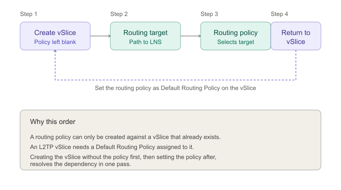
The order is: VSlice, Routing Target, Routing Policy, VSlice.
The VSlice is touched twice. The first time you create it. The second time you return to it and set the Default Routing Policy.
Why the VSlice Is Touched Twice
There is a circular dependency between the VSlice and the Routing Policy:
- A Routing Policy is created against a VSlice, so the VSlice has to exist first.
- An L2TP VSlice needs a Default Routing Policy assigned to it.
The portal resolves this by letting you create the L2TP VSlice with the Default Routing Policy left blank. Once the Routing Target and the Routing Policy exist, you return to the VSlice and set the Default Routing Policy to the one you just created.
The Steps
Step 1: Create the VSlice. Create the L2TP VSlice. Leave the Default Routing Policy field blank. Save.
Step 2: Create the Routing Target. Create the Routing Target against the L2TP VSlice from Step 1. For production deployments this is typically a VPN target pointing at the LNS. The Routing Target itself behaves exactly as it does for an Integrated VSlice. There are no L2TP-specific Routing Target fields.
Step 3: Create the Routing Policy. Create the Routing Policy against the same L2TP VSlice. Add an uplink rule that forwards traffic to the Routing Target from Step 2. The Routing Policy itself, including its rules, match patterns, and edit behaviour, is the same as for an Integrated VSlice. You can return to the policy later and add or change rules; switching between Routing Targets in those rules works the same way it always has.
Step 4: Return to the VSlice. Edit the VSlice from Step 1. Set Default Routing Policy to the policy you created in Step 3. Save.
The VSlice now has a complete configuration and knows how to reach the LNS. The remaining setup (LAC entries, LNS entries, Endpoint Group, Endpoints) follows on from here.
What Has Not Changed
- Routing Targets are the same. Same fields, same target types (VPN, Internet, WireGuard, Peering), same behaviour.
- Routing Policies are the same. Same rule structure, same match patterns, same direction logic. You can edit rules on a policy after it is in use, the same way you always have.
- Switching a rule from one Routing Target to another works the same way.
The only change is the location where the Routing Policy is selected. On an Integrated VSlice, it is selected at the Endpoint Group level, whereas on an L2TP VSlice, it is selected at the VSlice level. This difference introduces a dependency between configuration steps, which is addressed by following the four-step sequence outlined above.
Vantiq Motors Example
Vantiq Motors creates Vantiq Diagnostics L2TP as an L2TP VSlice with the Default Routing Policy left blank. They create a VPN Routing Target back to their data centre. They create a Routing Policy on the same VSlice with an uplink rule forwarding all traffic to that VPN target. They then return to the VSlice and set Default Routing Policy to the policy they just created. The VSlice is now configured. From this point, adding LAC entries, LNS entries, the Endpoint Group, and the SIMs themselves is straightforward.
Updated 2 months ago