
L2TP Setup
This page walks through the full configuration of an L2TP VSlice in the Customer Portal, with every field on every screen explained. If you have not configured L2TP on Stacuity before, read VSlice L2TP Concepts first to understand the components and the dependency between the VSlice and the Routing Policy.
The LAC and LNS field detail is split out into the LAC and LNS Reference page. This page covers the flow and the surrounding fields.
The Order
You will configure objects in this order:
- Create the L2TP VSlice. Leave the Default Routing Policy blank.
- Create a Routing Target that points towards the LNS.
- Create a Routing Policy on the L2TP VSlice and add an uplink rule forwarding traffic to the Routing Target.
- Edit the L2TP VSlice and select the Routing Policy as the Default Routing Policy.
- Add LAC addresses to the VSlice.
- Add LNS addresses to the VSlice.
- Create an Endpoint Group on the L2TP VSlice and select which LAC the group uses.
- Assign Endpoints to the Endpoint Group.
The sequence is important. Steps 1 through 4 outline how the dependency is resolved. Refer to the L2TP Setup Order diagram for details.
Vantiq Motors -- Example
Vantiq Motors is setting up an L2TP VSlice called
Customer-L2-VS01that will tunnel diagnostics traffic from their connected vehicle fleet back into their data centre over an existing VPN. The walkthrough uses their values where useful.
Step 1: Create the L2TP VSlice
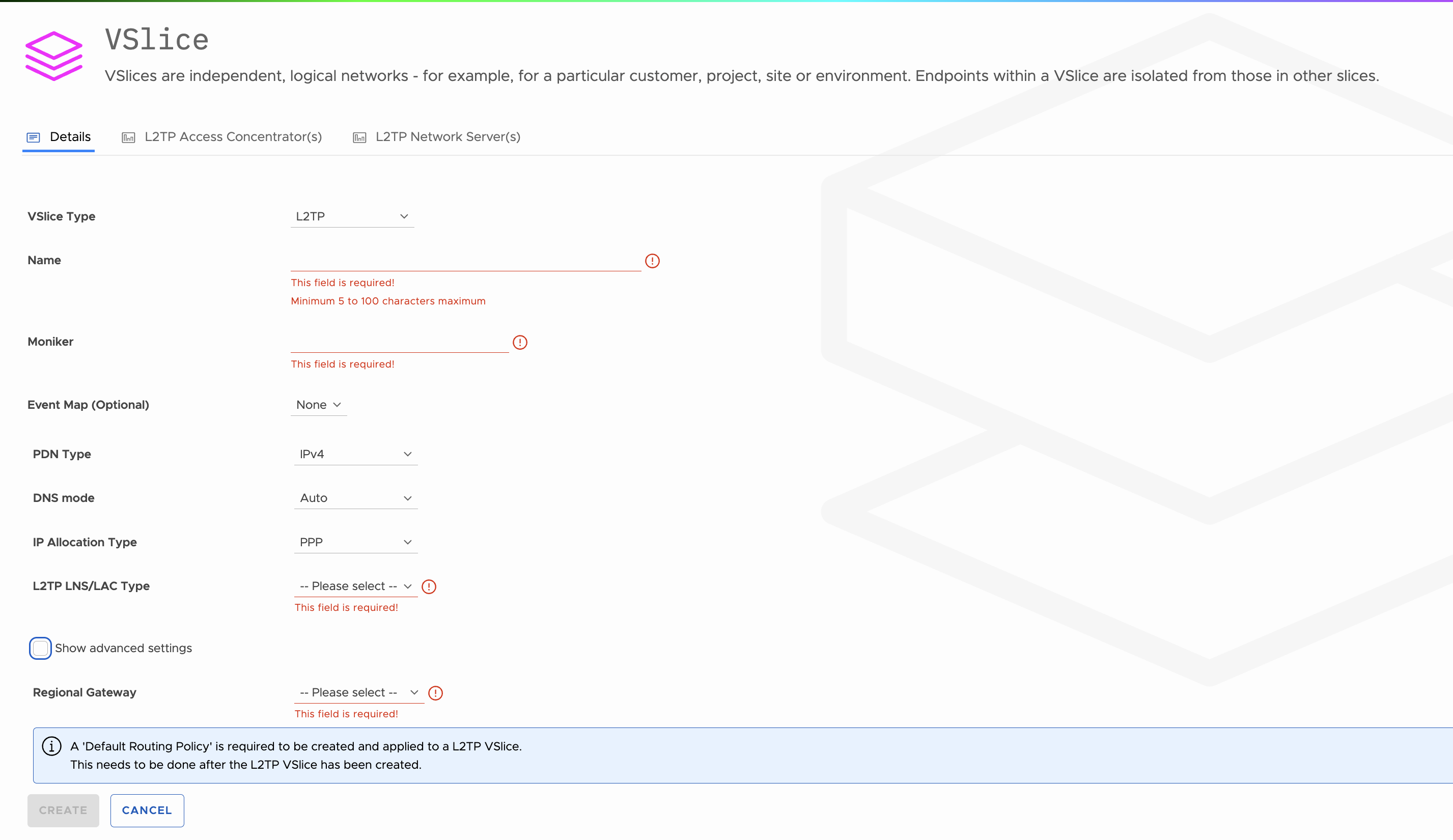
Go to VSlices in the Customer Portal sidebar. Select Add.
The Add VSlice form opens with a Details tab, plus L2TP Access Concentrator(s) and L2TP Network Server(s) tabs that become populated after the VSlice is saved. Start on the Details tab.
VSlice Type
| Option | When to Use |
|---|---|
| Integrated | The VSlice uses Stacuity for IP allocation, DNS, and routing. This is the standard option. |
| L2TP | The VSlice tunnels traffic to a customer-operated LNS, which assigns IP addresses to devices. |
Select L2TP. The form fields update to show the L2TP set.
Identification Fields
| Field | What to Enter | Validation |
|---|---|---|
| Name | A descriptive name for the VSlice. | Required. Minimum 5 characters, maximum 100. |
| Moniker | A short identifier used in URLs and API references. Auto-generated from the Name; you can override it. | Required. |
Including the type in the Name (for example, ending with
L2TP) is useful because the VSlice picker on other forms does not currently show the type next to the name.
Standard Fields
These appear regardless of type and behave the same as on an Integrated VSlice.
| Field | What to Enter |
|---|---|
| Event Map (Optional) | Choose an event map if you want events generated by this VSlice routed through a specific handler set. Defaults to None. |
| PDN Type | The Packet Data Network type. IPv4, IPv6, or IPv4v6 as appropriate. The screenshot shows IPv4 by default. |
| DNS mode | DNS handling for the VSlice. Defaults to Auto. |
| IP Allocation Type | Fixed to PPP for L2TP VSlices. PPP is currently the only allocation mode supported. |
L2TP-Specific Field
| Field | What to Enter | Notes |
|---|---|---|
| L2TP LNS/LAC Type | IPv4 or IPv6. The IP version used between the LAC and the LNS. | Required. |
Info Banner About the Default Routing Policy
The form shows an info banner that reads:
A 'Default Routing Policy' is required to be created and applied to a L2TP VSlice. This needs to be done after the L2TP VSlice has been created.
This is the dependency behaviour. The Default Routing Policy field appears further down the form (under Show advanced settings) but you leave it blank for now and set it in Step 4.
Show Advanced Settings
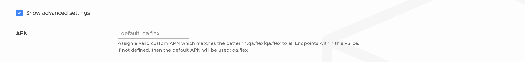
Tick the Show advanced settings checkbox. The form expands to reveal the L2TP, PPP, and gateway fields below.
APN
| Field | What to Enter | Notes | |
|---|---|---|---|
| APN | A custom APN matching the tenant's APN pattern (for example `*.qa.flex | qa.flex). Leave blank to use the tenant default APN (for example qa.flex`). | Updating the active APN will reprovision and reset all Endpoints in this VSlice. The portal shows a warning banner above the field when an APN is in use. |
The APN value must follow the same pattern rules used on the tenant. The pattern shown in the form (for example *.qa.flex|qa.flex) is determined by the tenant configuration.
L2TP Tunnel Parameters
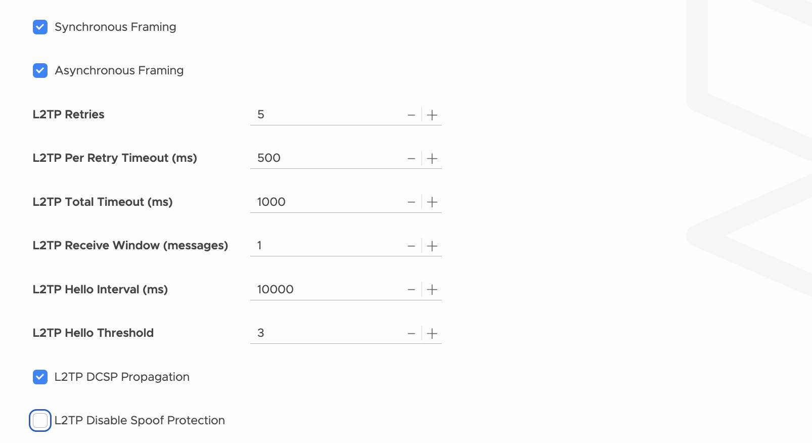
These control how the L2TP tunnel between the LAC and the LNS is brought up and kept alive. The defaults shown below are what the form ships with.
| Field | Default | What It Controls |
|---|---|---|
| Synchronous Framing | Enabled | Whether L2TP frames are sent synchronously. Match your LNS configuration. |
| Asynchronous Framing | Enabled | Whether L2TP frames are sent asynchronously. Match your LNS configuration. |
| L2TP Retries | 5 | The number of times the LAC retries failed L2TP control messages before giving up. |
| L2TP Per Retry Timeout (ms) | 500 | How long the LAC waits for a response before counting that attempt as a failed retry. |
| L2TP Total Timeout (ms) | 1000 | The total time budget for an L2TP operation, across all retries. |
| L2TP Receive Window (messages) | 1 | The size of the receive window used in the L2TP control channel, measured in messages. |
| L2TP Hello Interval (ms) | 10000 | How often the LAC sends a Hello keepalive on the tunnel. |
| L2TP Hello Threshold | 3 | The number of missed Hellos before the tunnel is considered down. |
| L2TP DCSP Propagation | Off | When enabled, DSCP markings are propagated through the tunnel. |
| L2TP Disable Spoof Protection | Off | When enabled, the L2TP layer will not enforce its built-in spoof protection. Leave off unless your LNS specifically requires it. |
These are standard L2TP protocol parameters. The values must agree with your LNS. Consult your LNS documentation and the L2TP RFC for what is appropriate to your deployment.
PPP Session Parameters
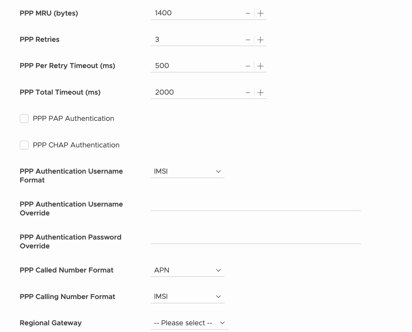
These control the PPP session that runs inside the tunnel.
| Field | Default | What It Controls |
|---|---|---|
| PPP MRU (bytes) | 1400 | Maximum Receive Unit for PPP frames. |
| PPP Retries | 3 | Number of PPP negotiation retries before giving up. |
| PPP Per Retry Timeout (ms) | 500 | Wait time per PPP retry. |
| PPP Total Timeout (ms) | 2000 | Total time budget for PPP negotiation. |
| PPP PAP Authentication | Off | Enable PAP for PPP authentication if your LNS uses it. |
| PPP CHAP Authentication | Off | Enable CHAP for PPP authentication if your LNS uses it. |
PPP Authentication and Identity Fields
| Field | Default | What It Controls |
|---|---|---|
| PPP Authentication Username Format | IMSI | The format used for the PPP authentication username when no override is set. IMSI is the default. |
| PPP Authentication Username Override | Empty | If set, this username is used for PPP authentication instead of the format-derived value or the IPN-supplied value. |
| PPP Authentication Password Override | Empty | If set, this password is used for PPP authentication instead of the IPN-supplied value. |
| PPP Called Number Format | APN | The format used for the called number presented to the LNS. |
| PPP Calling Number Format | IMSI | The format used for the calling number presented to the LNS. |
The PPP credentials must exist on the LNS in the format the LNS expects. If your LNS authenticates by IMSI, leave the Username Format on IMSI. If it authenticates by username and password, fill the override fields with credentials configured on the LNS.
Regional Gateway
| Field | What to Enter | Notes |
|---|---|---|
| Regional Gateway | The Stacuity edge site the tunnel originates from. The screenshot shows Europe (Frankfurt). Other options in production include Brazil, Australia, and Singapore. | Required. The tunnel from Stacuity to your LNS originates from this edge site. This setting applies to all Endpoint Groups attached to this VSlice. Pick the site nearest to your LNS for the lowest latency. |
Default Routing Policy
| Field | What to Enter |
|---|---|
| Default Routing Policy | Leave blank for now. The form shows the hint "A Routing Policy needs to be created on the VSlice and can then be selected." This will be set in Step 4 once the Routing Policy exists. |
Save the VSlice
Select Create. The VSlice is created.
The VSlice exists, but it has no Default Routing Policy yet, no LAC entries, and no LNS entries. The next steps add those.
Step 2: Create the Routing Target
The Routing Target is how the LAC reaches the LNS. For production, this is almost always a VPN.
Go to Routing Targets in the sidebar. Select Add.
| Field | What to Enter | Why |
|---|---|---|
| VSlice | The L2TP VSlice from Step 1. | Routing Targets are scoped to a VSlice. |
| Name | A descriptive name, for example LNS VPN Target. | Shown in the Routing Policy rule editor when you forward traffic to this target. |
| Region | The region the target is anchored to. | Should align with the Regional Gateway selected on the VSlice. |
| Redundancy Zone | The redundancy zone the target uses. | Standard Routing Target field. |
| Type | The target type. VPN for production. Internet is acceptable for testing only. WireGuard and Peering are also available. | The target type determines how traffic from the LAC reaches the LNS. VPN is private and authenticated; Internet is open. |
If you select VPN, additional VPN configuration fields appear (peer addresses, encryption settings, pre-shared keys, and so on). These are the standard VPN Routing Target fields and behave identically to Integrated VSlice usage. They are not L2TP-specific. See the Routing Targets documentation for the full VPN field reference.
Select Save. The Routing Target is created and the VPN, if applicable, will come up.
There are no L2TP-specific Routing Target fields. The only thing that matters for L2TP is that the target reaches your LNS.
Step 3: Create the Routing Policy
The Routing Policy defines what traffic gets forwarded where. For L2TP, you need at minimum one rule that forwards uplink traffic to the Routing Target you just created.
Go to Routing Policies in the sidebar. Select Add.
Policy Header Fields
| Field | What to Enter | Why |
|---|---|---|
| VSlice | The L2TP VSlice from Step 1. | Only Routing Policies attached to a VSlice can be set as that VSlice's Default Routing Policy. |
| Name | A descriptive name, for example L2TP Default Policy. | Shown in the VSlice's Default Routing Policy picker. |
| Status | Active. | An inactive policy will not forward traffic. |
Select Save. The empty policy is created. Now add the rule.
Add a Rule
Open the policy and select Add Rule.
| Field | What to Enter | Why |
|---|---|---|
| Match | All traffic, or a destination match pattern. | Use All traffic for simple deployments where every device sends every packet down the same VPN. Use a match pattern if you want different traffic to go to different targets. |
| Direction | Uplink. | The LAC needs to send traffic outbound to the LNS. |
| Action | Forward to. | Sends matching traffic to a Routing Target. |
| Target | The Routing Target from Step 2. | This is what binds the policy to the LNS path. |
Select Save and Apply.
If you need redundancy at the policy level, for example a primary VPN and a fallback VPN, add additional rules with destination match patterns. The matching behaviour is the same as for Integrated VSlices.
Step 4: Set the Default Routing Policy on the VSlice
This is the step that resolves the dependency cycle.
Return to VSlices. Open the L2TP VSlice from Step 1. Select Edit.
Tick Show advanced settings to expose the Default Routing Policy field.
| Field | What to Enter |
|---|---|
| Default Routing Policy | The Routing Policy from Step 3. |
The Default Routing Policy picker only shows policies attached to this VSlice, so the policy you just created should be the only option (or one of a small number, if you have already created others).
Select Update.
The VSlice now knows how to reach the LNS. The next step is to declare the LAC and LNS addresses themselves.
Step 5: Add LAC Addresses
Open the L2TP VSlice. Go to the L2TP Access Concentrator(s) tab.
The tab shows a Virtual LAC Address(es) table with columns for Address, Port, Tunnel Secret, and Action. Select Add LAC Address to add a row, fill in the fields, and use the save icon in the Action column to commit the row.
The detailed field reference, including the validation rules, the multi-LAC redundancy model, and the tunnel secret behaviour, is on the LAC and LNS Reference page. At a glance:
- Address. The IP that Stacuity will use as the LAC endpoint of the tunnel.
- Port. Defaults to 1701 (the standard L2TP port).
- Tunnel Secret. The shared secret used to authenticate the tunnel.
Use the trash icon in the Action column to remove a row. Add additional LAC entries if you want primary and secondary LACs.
Step 6: Add LNS Addresses
Still on the L2TP VSlice, go to the L2TP Network Server(s) tab.
The tab shows an LNS Address(es) table with columns for Preference, Address, Port, Retries, Recovery Interval, and Action. Select Add LNS Address to add a row, fill in the fields, and use the save icon to commit the row.
Detailed field reference is on the LAC and LNS Reference page. At a glance, with the form defaults shown for a fresh row:
- Preference. An integer ordering the LNS entries; lower values are preferred. Example: 1 for primary.
- Address. The IP of your LNS.
- Port. Defaults to 1701.
- Retries. The number of retries before giving up on this LNS. Default is 5.
- Recovery Interval. How long to wait, in milliseconds, before retrying a failed tunnel bring-up. Default is 30000 ms (30 seconds).
Add LNS entries as needed to support failover.
Step 7: Create the Endpoint Group
Go to Endpoint Groups. Select Add.
VSlice Selection
| Field | What to Enter | Notes |
|---|---|---|
| VSlice | The L2TP VSlice. | Selecting an L2TP VSlice changes which fields appear below. |
Once an L2TP VSlice is selected, three Integrated-style fields are hidden because they are now set on the VSlice itself:
- Routing Policy. Hidden. Set on the VSlice as Default Routing Policy.
- Regional Gateway. Hidden. Set on the VSlice.
- Regional Policy. Hidden. Set on the VSlice.
A new field appears that does not exist for Integrated VSlices.
L2TP-Specific Endpoint Group Field
| Field | What to Enter | Why |
|---|---|---|
| L2TP Access Concentrator | One of the LAC entries declared on the VSlice. | Each Endpoint Group binds to one LAC. If you want different sets of devices to use different LACs (for redundancy or load distribution), create multiple Endpoint Groups, one per LAC. |
Standard Endpoint Group Fields
These behave the same as for Integrated VSlices.
| Field | Behaviour |
|---|---|
| Subscription Type | Integrated or Edge. Integrated SIMs authenticate on the Stacuity core. Edge SIMs authenticate elsewhere and route through L2TP. Both are supported. |
| IPN | Primary and secondary IPN groups, same as Integrated. |
| Operator Policy | Same as Integrated. Steers SIMs to different networks at session bring-up. |
| Event Maps | Same as Integrated. Configure event handlers as usual. |
| Session Activity Time | The inactivity period after which a session triggers an action. |
| Session Inactivity Action | Notify, or Notify and Terminate. Notify and Terminate raises an event and terminates the session at the P-gateway. |
Save the Endpoint Group
Select Save.
If you need primary and secondary LAC redundancy, add a second Endpoint Group now, identical except that it selects the secondary LAC. Place half the fleet in each group.
Step 8: Assign Endpoints
Endpoint assignment for L2TP works the same as for Integrated. Select the Endpoints (SIMs) you want in this VSlice and assign them to the Endpoint Group.
Once a SIM in this group attaches to the network, Stacuity establishes the L2TP tunnel to the LNS (if not already up), opens a PPP session inside the tunnel for that SIM, and the LNS allocates an IP address. Traffic from the device travels inside the tunnel to your network.
In the Endpoint Group view, the IPv4 and IPv6 columns are not populated for L2TP Endpoints because Stacuity does not assign those addresses. The address is determined by the LNS, and the address change button on the Endpoint is disabled.
Verification
Once everything is configured, verify in this order.
- Confirm the Routing Target is established. For VPN targets, this means the VPN status is Up.
- Confirm the L2TP VSlice has a Default Routing Policy set.
- Confirm the VSlice has at least one LAC and one LNS entry, with addresses and ports that match what your LNS expects.
- Confirm the Endpoint Group has an L2TP Access Concentrator selected.
- Bring up a test SIM and confirm the LNS allocates an address. The Endpoint Group view will show the LNS-provided label rather than a numeric address; the actual address can be confirmed from the device or from the LNS.
If a session does not come up, the most common causes are: PPP credentials mismatched between the override fields and the LNS user database, tunnel secret mismatched between the LAC entry and the LNS configuration, or the Routing Target not actually reaching the LNS IP.
What Cannot Be Changed Later Without Rebuilding
Some choices on an L2TP VSlice are effectively fixed once devices are using it.
- The Regional Gateway. The tunnel originates from this site. Changing it would mean tearing down all tunnels and rebuilding from a different edge.
- The L2TP LNS/LAC Type (IPv4 or IPv6). Changing this changes the protocol used end to end.
- The VSlice Type itself. You cannot convert a VSlice between Integrated and L2TP.
Other settings, including LAC entries, LNS entries, advanced L2TP and PPP parameters, and the Routing Policy rules, can be edited after the VSlice is in service. Changes take effect on the next tunnel bring-up.
Editing the APN deserves a separate caution: updating the active APN will reprovision and reset all Endpoints in the VSlice. Make APN changes during planned maintenance windows.
Deletion Rules
The standard rules apply. A VSlice cannot be deleted while Endpoint Groups, Routing Policies, or Endpoints are still associated with it. Remove the dependants first. The deletion order is the reverse of the setup order: unassign Endpoints, delete the Endpoint Groups, delete the Routing Policy, delete the Routing Target, delete the VSlice.
Updated 2 months ago